
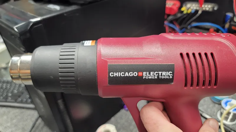
I recently had the need to use my Harbor Freight (Chicago Electric) heat gun to remove some stickers on a cabinet I was refinishing. I pulled the gun out of my toolbox and plugged it in and nothing, no lights, not power indication, nothing!
I tried another outlet – same results! It was working when I put it away 🙁

I removed the screws, removed the case half to inspect the internals.

First thing: I checked the fuse and mapped out the internal components. The fuse was good.
If you follow the Line input, it is tied to DC minus. The neutral leg passed through R1 a 250K ohm resistor to the fuse then to the junction of D1/D3 (rectifiers) then to the cathode of a TVS diode (D2), operating in avalanche mode. The DC is filtered and fed to the input of the 7805 voltage regulator on to the PIC micro-controller.
What you don’t see in the image above is the 2.2uF capacitor in parallel with R1 located on the backside of the board. This capacitor is known as a “dropping capacitor” in the transformer-less power supply.
With this type of DC supply, you must be very careful when testing as there is no galvanic isolation of the mains so the entire board is “hot” with reference to line voltages and creates an electrocution hazard! Even the DC minus is tide to the mains so proceed are your own risk!
I carefully plugged the unit in and checked for DC input at the regulator and only had 3.2 volts DC. I check for AC voltage across the mains and measured 122 VAC. I checked for voltage at the fuse and measured 1.8 VAC, clearly a problem.
Transformerless Power Supply Calculations
Input Parameters: C = 2.2 µF, Vin = 122V AC
1. Capacitive Reactance (Xc)
Formula: Xc = 1 / (2 × π × f × C)
- At 60 Hz: Xc = 1 / (2 × 3.14159 × 60 × 2.2×10-6) = 1,205.72 Ω
- At 50 Hz: Xc = 1 / (2 × 3.14159 × 50 × 2.2×10-6) = 1,446.86 Ω
2. Maximum Available AC Current (Imax)
Formula: Imax = Vin / Xc
- At 60 Hz: Imax = 122 / 1,205.72 = 0.10118 A = 101.2 mA
- At 50 Hz: Imax = 122 / 1,446.86 = 0.08432 A = 84.3 mA
3. Unregulated Peak DC Voltage (Vpeak)
Formula: Vpeak = (Vin × √2) – Vdiode_drop
- Calculation: Vpeak = (122 × 1.4142) – 1.4 = 172.53 – 1.4 = 171.1 V DC
| Parameter | 60 Hz (e.g., US) | 50 Hz (e.g., EU) |
|---|---|---|
| Capacitive Reactance (Xc) | 1,205.72 Ω | 1,446.86 Ω |
| Max AC Current (Imax) | 101.2 mA | 84.3 mA |
| Unregulated Peak DC Voltage | 171.1 V DC | 171.1 V DC |
As you can see, the max current through the dropping capacitor limits the current to roughly 101mA. With the TVS diode in line, it drops the voltage to the regulator to approximately, 20 VDC. The question is: Why only 3.2V to the input of the regulator? To answer that, I need to verify if there was an up-stream short or issue causing the voltage drop.
I removed the TVS diode, regulator and dropping capacitor. I checked all three and found an issue with the capacitor

Even though the capacitance measured okay, look at the ESR. This is high for a Metallized Polypropylene Capacitor. Very suspect!
I looked through my stash of poly caps and found a 3.5uF at 250V, that should work!
It was a little large but i was able to solder it in for testing:

Also re-installed D2 and U1 for the test. It worked!
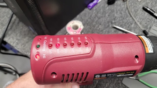
I found some replacements on Amazon rated for 630V

It fit into the case – no issues:

Reassembled it – and all working as intended!
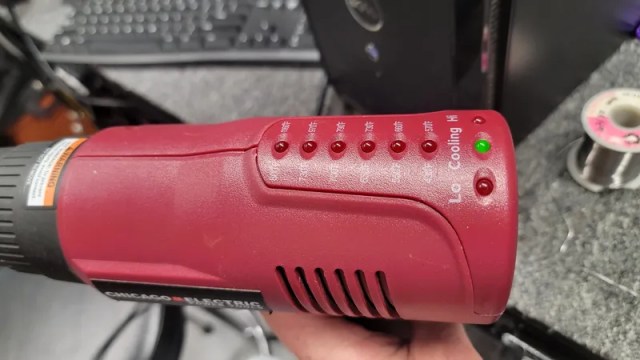
The fix – a faulty 2.2uF dropping capacitor in the transformerless supply. Hope this may help someone else.
Interesting post. Thanks for the share!