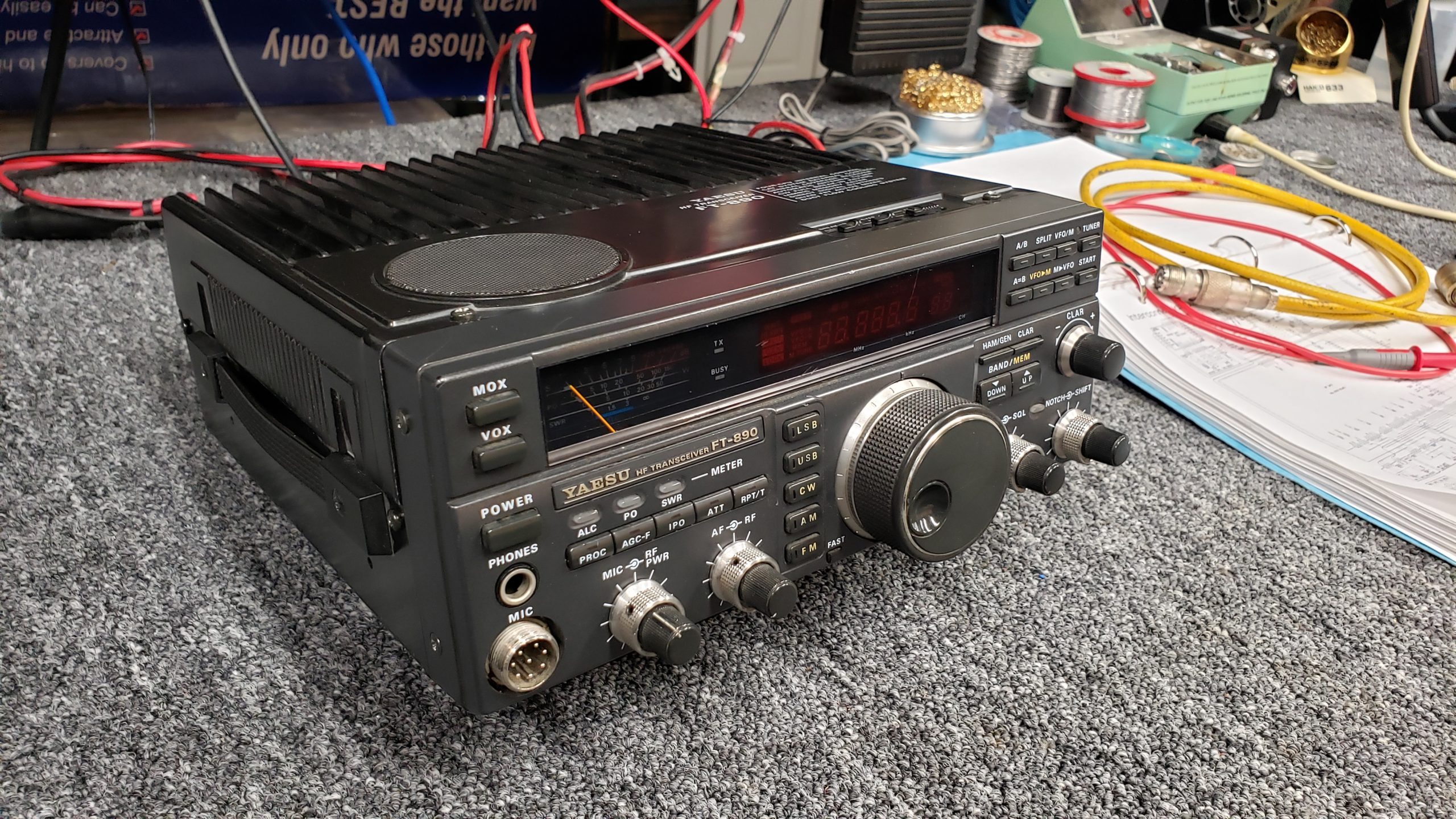
A great radio from the past! I remember when I first got licensed, several friends had these radios and I was always impressed with their compact size and amazing receiver and audio quality.
Talking to a fellow HAM on a local repeater, we discussed the fact he had just passed his General Class test and was excited about getting on the air. However, he explained that his HF radio had issues. We talked about those issues and I offered to take a look at the radio for him. This is a brief post showing some pictures and a video I took during the repair.
The radio looked like it was in pretty good shape when it arrived. Although, it was in a basket. I guess this would qualify as a basket case?? I performed some preliminary function tests and found the radio would power on but had no receiver activity, no receive audio and no RF output. As the story goes, the radio had previous issues with the reference oscillator and a frequency stability issue. I was told that the finals had been previously replaced by a repair facility. Apparently, the person that had replaced the finals had removed the internal antenna tuner and told the original owner that it was the cause of the failure and decided to remove it from the radio.

Digging in, I opened the radio to do some basic inspection. I found the auto tuner had been reinstalled but none of the harnesses where physically connected. After a few checks, I realized this was going to take some time. There was evidence that the radio had seen multiple repair attempts and I needed to familiarize myself with the service manual and schematics.

After an hour of reading through the manual, I decided that based on the various symptoms the radio was experiencing, I suspected a possible voltage supply issue. I started by checking power input to the various boards. There are several regulators in this radio and doing some simple voltage checks, determined what appeared to be normal voltages. I verified that the grounds were good in the appropriate places.
After the voltage tests, I started looking for a heartbeat. The reference oscillator seemed to be somewhat erratic. I remember one of the mentioned issues from the past, was a problem with TC1002 the trimmer cap for the reference oscillator. Looking close, it looked like someone had been there before. I decided to remove the local Unit and look at the components on the bottom side of the board (where the real business takes place).
Inspecting the bottom side of the board I found some poor solder connections to some of the SMD components for the LO. I cleaned up the connections, tested Q1002 and Q1003 shown in the picture below. After reinstalling the board I was able to get a stable LO but this wouldn’t account for the symptoms the radio had. But divide and conquer! I continued troubleshooting. I then checked the 2nd LO and it was fine.


Moving down the chain, I checked the DDS and found no output on transmit. The other clues noted were no TX relays heard during transmit. The only indicator was the TX LED would light.

In review of the schematic, I decided to start checking for inputs to the Local Board. This is where clue three came in. I didn’t have clock signals to the Sub DDS board and was missing PTT input signals. While probing some of the connectors on the board, I realized something, there are several plugs that have the same pin count and they can be physically connected to any connectors with the same number of pins on the board! Really??

As you can see in the image above, the only difference is, pin one of each connector has a colored wire. This is shown on the interconnect diagram below.

This is when I realized that there were three harnesses plugged into the wrong places on the board. I spent the next hour reviewing all of the connectors to make sure everything was in the correct place. After doing so, I thought I would take a break. Looking back at the bench, this is what I saw:


Hmmmm…. Carnage everywhere and I didn’t even hear the explosion 🙂
The good news is, the radio came alive! It had receive audio, pretty decent sensitivity and the transmitter had RF out!!
I removed the automatic antenna tuner and performed some basic inspections. I ran through the capacitor alignment procedure in the manual and this verified that at least the tuner controller and motors where working. I also checked the on-board relays for the inductors and they seem to all function fine.

I sorted through the harness connectors for the auto tuner and cleaned up the harness routing seen below.

Here is an image of the auto tuner back in the chassis.

During reassembly, I noted that the meter back-light seem really dim.

I decided to replace the incandescent bulb with an LED to brighten it up a little.

I continued reassembly and performed an alignment routine.

Finally, time to do some real testing…..
The FT-890 is back and in working order. I’m sure the owner will be excited to have it and will get some great use of it.
I’m always amazed at the generosity of the ham community. Over the years, I have been provided equipment from fellow hams when I had nothing and could barely provide for my family. To this day local hams in our community are still so willing to help the new guys. In this case, a well respected ham in our community, donated this radio to a newly licensed general class amatuer. What a great guy! And the true benefit, in a “pay it forward” way, this continues to grow! Another reason why amateur radio is so awesome!
Jim, that is a fantastic job on trouble shooting and finding harnesses plugged into the wrong places and correcting them, also very impressive how fast you were able to do all this in just a couple days since we brought my basket case to you to look at ;-p , I wasn’t sure if it would have all working and good parts in the radio. That’s great news that it’s in working condition and I can’t wait to get on the air with it. KJ7VZY the proud and very happy owner of this Yaesu FT-890, Thank you Jim.