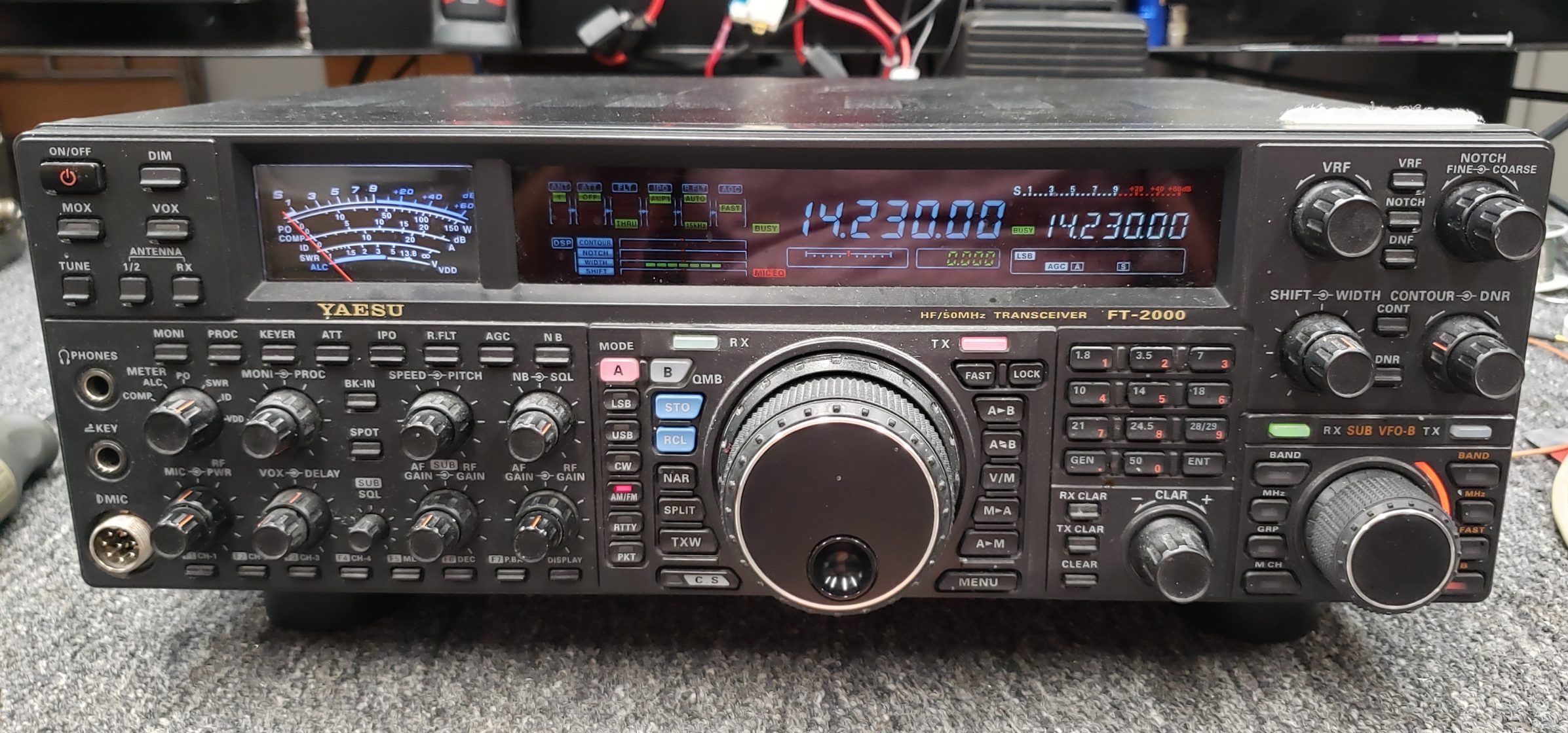
A beautiful radio with a problem! I received an email from a friend asking me to look at this radio. After receiving it, I decided to do a quick function test. I found it had a very low sensitivity on all the of the bands. I was able to inject a signal, and hear it but there was not any indication on the S-meter. I did note some improvement when activating RF preamp 1 and preamp 2. So, at least I know they were working.
Aside from a weak receiver, the transmit functions all seemed fine. So it was time to dig into the service manual and decide on a course of action.

Looking at the block diagram and knowing I had gain from the preamps, I decided to check the levels in and out of the 1st mixer stage.

According to the schematic, the 1st local oscillator is used to drive the gates of the mixer via a transformer.
I found the first mixer and noticed it was a double balanced FET device. The RF input and LO input signals were fine but the IF level was dismal.

Once I saw the actual device I was hoping it was good because it is really small and in a bit of tight location. Above is a picture of the device (6 leg device, center inside can).

Above is a close up. As it turned out, it was not good. There was little to no IF output. So this meant the mixer would need to be replaced.
The 1st mixer in this radio is a MMIC device in a MCPH6 package. It measures roughly 2mm by 2mm. In order to remove this device you really need a hot air station. I have seen video where some have used a soldering iron in an attempt to remove it. As a result damage to the PCB occurred. Also, there a other components within close proximity to this device and extreme care is required in order to avoid accidental damage or loss of these other components. Here is the data sheet on the device.
I used Kapton tape to cover the surrounding devices and only expose the device being removed. Sorry, I forgot to snap a picture.

Not the best picture but you can see the yellow tint of the Kapton Tape lining the inside of the box. Being careful with the heat, it doesn’t take much to dislodge other components. I was able to remove the old device seen here, stuck to the end of my tweezer.

A better view showing the size in comparison to a pen. No, that black thing is not something a fly left. It’s a double balanced mixer.

With the tape removed and the pad cleaned and ready for the new device, it was time to install the new part.

I added a small amount of flux and with a steady hand, (okay, I can’t lie, I was a little shaky) I was able to hand solder the new device into place.

Time for a test. It’s alive again!! Injecting a -73dBm signal provided a S9 S-meter reading. Time to blow out the dust, reassemble the radio, wipe it down and send it home!
One can only speculate on the cause of this failure. There have been other articles published on this radio and I have found some information regarding the modification of the preamp circuits to add some additional attenuation on the front end. Some of it information seems reasonable however I didn’t find anything specifically produced by Yaesu supporting any specific modification to this radio.
VERY FEW people could have performed this opperation with the skill and equipment needed to bring life back into the receivee!!! Great work!!!!